3D Truck Wheel Alignment
SY808
Best truck wheel alignment in factory is best precise and convenient wheel alignment for heavy duty vehicles. We are wheel alignment manufacturer in Shenzhen, China with factory area over 2000㎡. We have patented products cloud 3D wheel alignment, 5D wheel alignment, 3D truck wheel alignment, mobile 3D wheel alignment and mobile 5D wheel alignment.
Advantages of Best Truck Wheel Alignment in Factory:
5D technology overcomes all disadvantages of 2D technology, such as mismeasurement.low precision.human factors , which are caused by following reasons:
[1]Original errors caused by wheel rim deformation cannot be eliminated by compensation;
[2]Errors caused by wheel clamp deformation can not be eliminated;
[3]Precision of truck should be higher than that of cars, but 2D technology makes it lower;
[4]Different measurement results caused by different operational approaches and strength.
5D technology adopts anti-shake measurement technology. It can eliminate time errors caused by car body shake within 20 seconds, improving labor efficiency. Meanwhile, it avoids problems caused by wireless and high-frequency interference. It can be used at any indoor places.
Configuration list of Best Truck Wheel Alignment in Factory
|
model |
Sensor (1 ) |
Targets (8) |
Wheel clamp (8) |
Turntable (4) |
frame offset tool(1) |
Tablet PC(1) |
Wedge block(2) |
Cabinet(1) |
24inch wireless TV (1) |
|||
|
SY808 |
★ |
★ |
★ |
★ |
★ |
★ |
★ |
|
|
|||
|
SY808A |
★ |
★ |
★ |
★ |
★ |
★ |
★ |
★ |
★ |
|||
Measurement Range and Accuracy of Best Truck Wheel Alignment in Factory:
|
References |
Accuracy |
Measurement Range |
Measurement TotalRange |
|
Camber |
±0.02° |
±8° |
±8° |
|
Caster |
±0.05° |
±19° |
±19° |
|
K.P.I |
±0.02° |
±19° |
±19° |
|
Toe |
±0.02° |
±22.5° |
±45° |
|
Turning Angle |
±0.08° |
±22.5° |
±45° |
|
Track width difference |
±0.03° |
±2° |
±8° |
|
Front Setback |
±0.02° |
±2° |
±4° |
|
Maximum Turning Angle |
±0.02° |
±45° |
±45° |
Comparison between CCD and Best Truck Wheel Alignment in Factory
CCD:

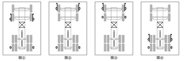
Step 1 Picture ① shows that reference is No.4 axle, adjust the toe of No.2 axle;
Step 2 Picture ② shows that reference is No.4 axle, adjust the toe of No.1 axle;
Step 3 Picture ③ shows that the drag link between No.1 and 2 axle makes No.1 and 2 axle parallel;
Step 4 Picture ④ shows that the adjustment of No.3 axle individual toe.
Remarks::When installing sensors, wheels need to be lifted to make run-out compensation.
*Your email address will not be published. Required fields are marked.
